Auto-Leveling Sweetness
Hey all,
2 week ago, I was able to install and test the new auto-leveling/tramming (whatever you want to call it) feature in the Marlin firmware. I always wanted to add this feature to the 3DPrintMi. I was always on the fence because I never felt confident in the servo/mechanical switch setup. There's too many moving parts involved for something that needed to read data consistently. Other setups came along like the auto touch Z end-stop and the FSR (Force Sensor Resistor) but impletenting them meant overhauling a few components. It wasn't until Printrbot introduced the induction probe which was a real game changer for me. After many hours of preparing, printing, and testing, I finally have a reliable setup.
After using the auto leveling feature, I'm actually blown away by the results. I'm getting better quality prints and consistent dimensional accuracy. For a long time, I was designing multi-part components with a +0.3mm allowance for clearance. Now I'm able to go as low as +0.1mm and still achieve a loose fit.
What sets my setup apart from the others is that I'm still able to print on a glass plate. Read on and I'll show you how to pair an induction probe with a glass plate.
2 week ago, I was able to install and test the new auto-leveling/tramming (whatever you want to call it) feature in the Marlin firmware. I always wanted to add this feature to the 3DPrintMi. I was always on the fence because I never felt confident in the servo/mechanical switch setup. There's too many moving parts involved for something that needed to read data consistently. Other setups came along like the auto touch Z end-stop and the FSR (Force Sensor Resistor) but impletenting them meant overhauling a few components. It wasn't until Printrbot introduced the induction probe which was a real game changer for me. After many hours of preparing, printing, and testing, I finally have a reliable setup.
 |
| Full setup - Induction Probe with ducted fan cooling |
What sets my setup apart from the others is that I'm still able to print on a glass plate. Read on and I'll show you how to pair an induction probe with a glass plate.
Induction Probe
 |
| SN04-N probe |
For this auto leveling setup, I'm using the SN04-N induction probe instead of the NPN model probe Printrbot uses. There's a few reason why I went for this version:
- Smaller profile, doesn't take much space on the tool head (extruder mount)
- Relatively cheap, about $7.
- No need to reduce the output voltage, the rated DCV is within the electronic board spec (5V)
 |
| Connecting to the Printrboard |
Got really confused with the wiring. The schematics on the induction probe doesn't match up with the Printrboard. Here's how the wiring is done. (Blue = ground, Brown = input, Black = output)
 |
| Induction probe mount |
The low profile probe gave me more flexibility in locating a mounting spot . If I have gone with the NPN model, I would have to redesign my extruder mount, thus increasing the tool head profile. I had one mount hole to work with which was good enough for me. It sits really close to the heater block so I have to keep an eye on it in case it starts melting. *knock on wood*
Induction probe and glass plate setup
Now, the typical induction probe setup requires a metal plate in order for it to work. Most printers use an aluminum build plate as a build platform. I never had much success printing on an aluminum plate so I wasn't ready to give up the glass. Apparently, sticking an aluminum plate under the plate doesn't work. Bummer.
Since that didn't work, I tried:
Since that didn't work, I tried:
- Sticking aluminum foil under the glass plate
- 3mm thick aluminum sheet under the glass plate
- Stuck aluminum tape on four corners of the glass plate (detects but lose build volume)
Just when I was about admit defeat, I noticed my sensor would detect my steel spatula from a much greater distance, about an extra 2-3 mm. Doesn't seem a lot but it was worth testing. Luckily, I had a 28 gauge steel sheet lying around.....
 |
| Cut the 28 gauge steel sheet to the same size as the glass plate |
 |
| Steel sheet under glass plate, clamped with binder clips. |
Cut it down to size, clamped it under the glass plate, crossed my fingers, and homed the Z. Hell yeah! It works! Now I get to keep my glass and barely adds any mass to the build plate. A win win.
-Note -
Stainless steel sheets DO NOT WORK. Bought a pre-cut, 26 gauge stainless steel plate from onlinemetals.com and the probe just couldn't detect it. My poor printer crashed itself into the bed. The only difference between the two is that one is stainless while the other is galvanized. Galvanized steel just means it has a protective layer of zinc which is probably what the induction probe picks up instead. I have heard copper pcp works but they can be pretty expensive.Marlin Firmware Setup
If it wasn't for Thomas Sanladerer's youtube video and Zenmaster's blog, I wouldn't be able to get this going. Thank you guys! I made a pictorial guide for myself just in case I forget.


Results
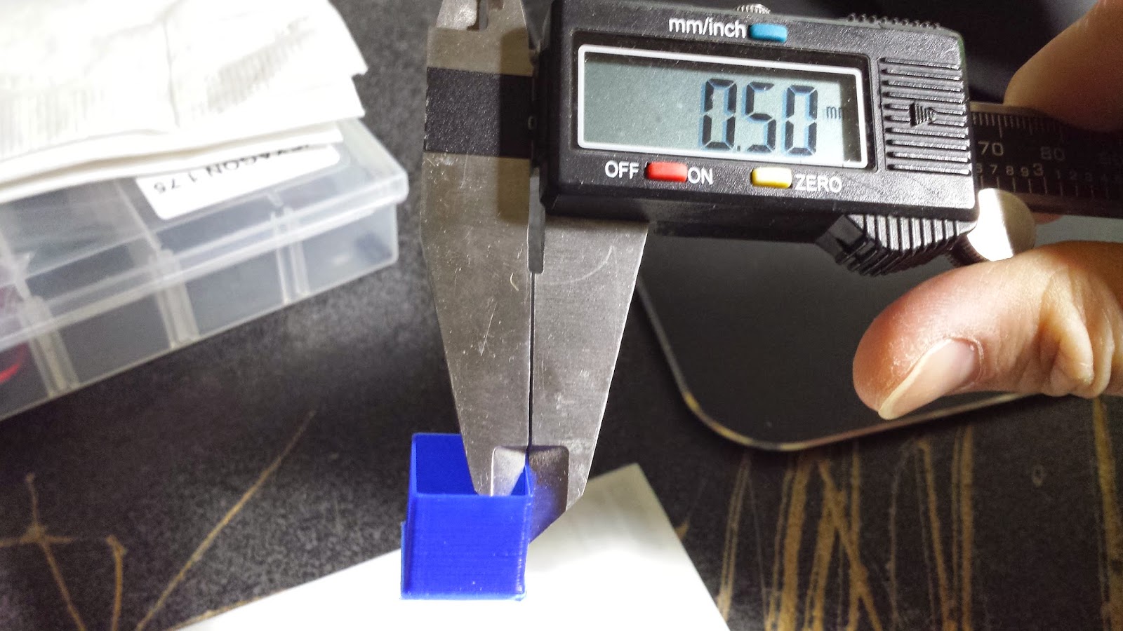 |
| thin wall calibration cube, measured 0.50mm on all 4 sides. I used to get 3 consistent readings and 1 way off. |
 |
| Custom hexagon fan shroud, top infill came out perfect. |
 |
| Tall prints remain consistent, no artifacts visible |
 |
| Walkaway cube test |
No comments:
Post a Comment